Engineering and Manufacturing
Engineering & Manufacturing
Flow Control and Letdown Systems (for integrated letdown systems)
History of Valve and Flow Regulation
The concept of controlling liquid flow dates back to ancient times, with the Romans using bronze plug cocks in their aqueducts. In the 18th century, James Watt, a Scottish inventor and mechanical engineer, developed the fly-ball governor as part of his focus in improving steam engines. This device used the engine speed and gravity to effectively regulate steam flow to the engine.
During the 19th century, control valves evolved alongside the growing use of steam. Self-contained pressure and level regulators were developed for steam boilers in power stations. Notable contributions came from inventors like William Fisher and William B. Mason.
By the early 20th century, control valve sizing began to standardize. In the 1960s, the Fluid Control Institute published sizing equations for both compressible and incompressible fluids. The focus of these equations was quite narrow, but it formed the basis of a range of standard equations and sizing procedures, published by International Society of Automation (ISA) and International Electrotechnical Commission (IEC). The ANSI/ISA-75.01.01 and IEC 60534-2-1valve sizing standards have been widely used since the 1970’s and have subsequently been harmonized.
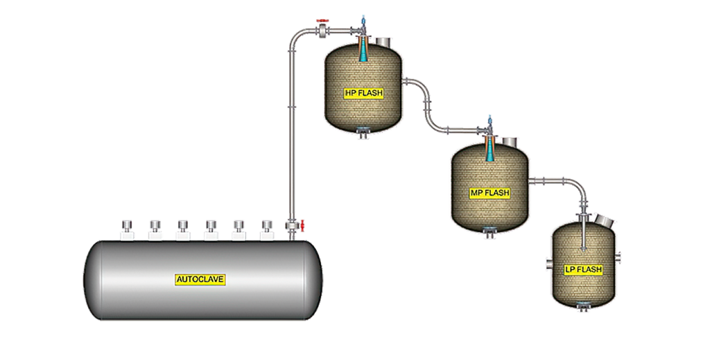
Integrated Letdown Systems
However, in applications with significant pressure drops, water may flash, generating steam which greatly increases volumetric flow. The linear velocity of the mixture increases to supersonic levels, after which a shockwave is formed. This shockwave plays a key role in energy dissipation, causing a sharp drop in velocity. It forms downstream of the valve’s choke point, and a blast tube is often used to contain or control the shockwave location and impact on the downstream equipment. Therefore, a system-level approach is required, integrating both the valve and the blast tube. Additional challenges such as solids abrasion, corrosion, and fluctuating operating conditions further complicate designs. To ensure a robust design, it is crucial to accurately predict the shockwave location across the system’s entire operating envelope.
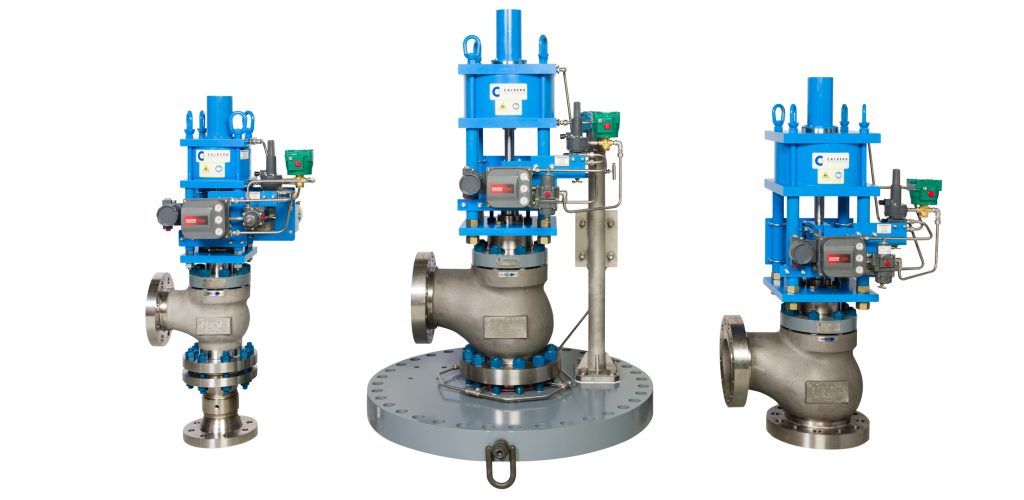
Caldera Engineering specializes in severe-duty flow control and pressure-reducing systems. Each system is custom designed for its specific application, often involving high pressure drops, cavitation, flashing, corrosive media, and solids. These applications do not lend themselves to the ISA or IEC procedures. Caldera employs proprietary Homogeneous Equilibrium Model (HEM) and Method of Characteristics (MOC) based software to predict the location and characteristics of shockwaves. Caldera also employs advanced Computational Fluid Dynamics (CFD) modeling to identify high-wear areas. The system geometry is then optimized, and specialized ceramics are applied in critical zones to ensure maximum durability and performance.